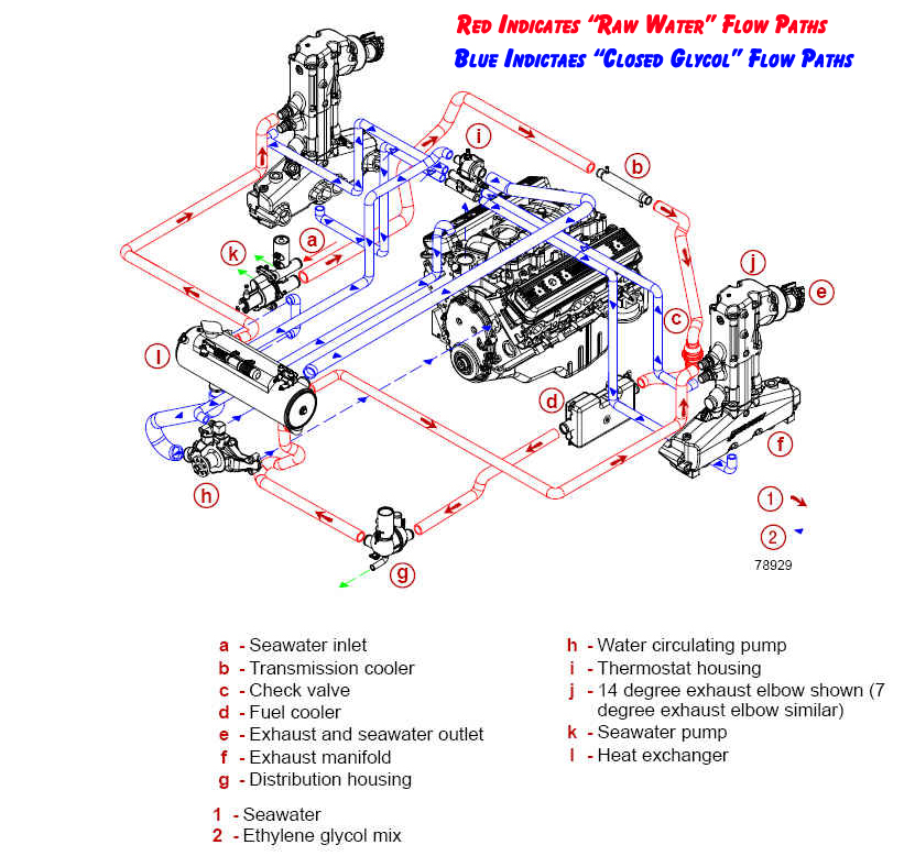
1989 2 3 Engine Cooling Diagram

1989 1989 J Engine Cooling System 2 8l V6 Lb6 2 8w Chevrolet Cav Top selling items for your 1989 stern drive 2.3 [ 232bmrmef ] view parts diagrams and shop online for 232bmrmef : 1989 stern drive 2.3. offering discount prices on oem parts for over 50 years. fast $4.95 shipping available. 1989 ranger 2.3 efi. the 2.3 engine wiring diagram illustration in the 1980 89 ford truck parts catalog shows temp sender to be on the drivers side of the engine block rear (not at the back of the engine, not in the head). the temp sender has been at this same location since at least 1978.

Schematic Diagram Of Engine Cooling System May 12, 2010. #6. re: 2.3 ltr omc ford overheating. take the hose from the transom that goes to the t stat housing (some of these have a power steering or oil cooler in line), remove it from the t stat housing and holding it facing up start the engine and you should have 3 or 4 inches of water coming out, if not then the problem is in the out. Received 44 likes on 42 posts. there is a pressure test you can do to pump up the coolant system pressure and look for leaks in the whole system. the tester replaces the radiator cap and you pump it to 15 16 psi. perhaps one of the auto supply stores loans them out. or will preform the test for you. Heater supply and return hose: the heater hose's main function is to transport coolant from the engine to the heater core which is located inside of the vehicle. heater tube assembly: keeps your coolant flowing perfectly and runs from the front of the intake manifold back to the rubber heater hoses on the heater core. The 1989 omc cobra wiring diagram depicts the entire wiring system. it is designed with distinct colors and symbols to identify each individual wire. at the center of the wiring diagram is the engine terminal block. this is where the ignition switch wiring routes to the power distribution panel. from here, the various wiring components branch.

Schematic Diagram Of Engine Cooling System Heater supply and return hose: the heater hose's main function is to transport coolant from the engine to the heater core which is located inside of the vehicle. heater tube assembly: keeps your coolant flowing perfectly and runs from the front of the intake manifold back to the rubber heater hoses on the heater core. The 1989 omc cobra wiring diagram depicts the entire wiring system. it is designed with distinct colors and symbols to identify each individual wire. at the center of the wiring diagram is the engine terminal block. this is where the ignition switch wiring routes to the power distribution panel. from here, the various wiring components branch. 1988 ford thunderbird 2.3l turbo wiring diagram (.pdf) 1988 1991 ranger 2.3l engine wiring diagram. 1987 1988 thunderbrid turbo coupe wiring diagram. 1990 ranger to 1988 turbo coupe wiring pinouts (excel spreadsheet) ford explorer 4.0l to bronco ii wiring. 5.0l electronic fuel injection (efi) wiring. Fits: 2.3, 3.0, 4.3 (1986 90) & 2.5 (1986) 18 5433d features ★ oil filled for better cooling and long life ★ low resistance and improved turn ratios produces the higher voltage needed to run larger spark plug gaps for added power and better fuel economy ★ more windings maximize energy and reliability over the full rpm range.

Comments are closed.