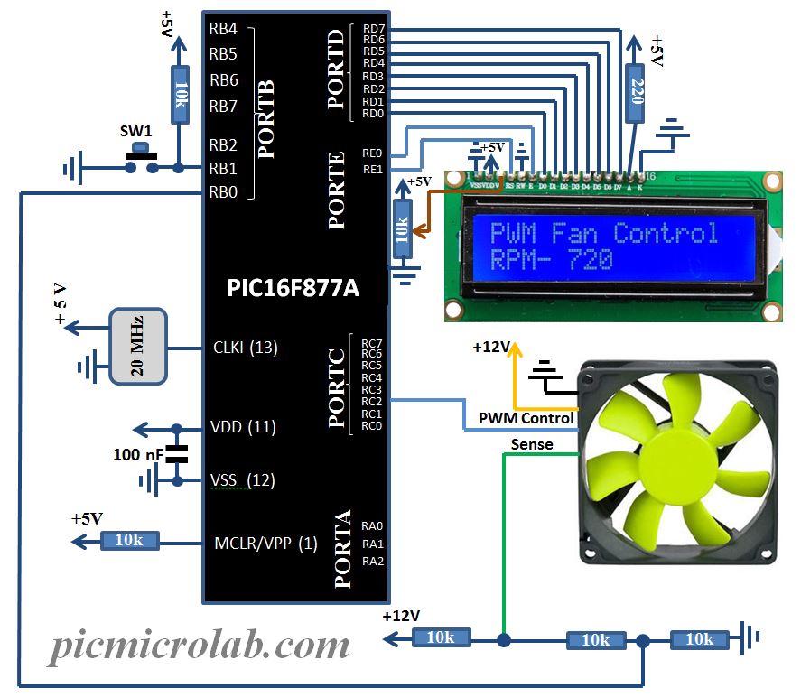
Cooling Fan Controller Circuit Diagram

Automatic Cooling Fan Controller Circuit Diagram A fan controller schematic refers to the circuit diagram or design of a fan controller. it outlines the components and connections required to build the fan controller. this schematic can be used by electronics enthusiasts and professionals to build their own fan controllers or to understand the internal workings of existing controllers. These two types of speed control circuits are found in the table below. integrated fan controller. discrete fan controller. 2 wire. an external fet is used to drive the fan. speed control can only be implemented with power measurement. fan driven with adjustable pwm signal and external fets. speed control can only be implemented with power.

Cooling Fan Speed Control Circuit Step 2: connect all parts as the image above. this circuit uses a thermistor as a sensor, the thermistor resistance decrease when a temperature increase. when the temperature increases the thermistor resistance decrease until the voltage set point that adjusts by potentiometer higher than vgs threshold, mosfet change to on state and make a 12. Fan control circuits range from simple switches that boost the fan speed at a certain temperature, to digitally controlled fans with continuously variable speed. high speed low speed switches are inexpensive, but the sound of sudden speed changes can be annoying. digitally controlled fans perform well, but those circuits are more costly, and. Figure 2 shows the differences between 3 wire and 4 wire fan circuits. figure 2. 3 and 4 wire fans. fan control. no control: the simplest method of fan control is not to use any at all; just run a fan of appropriate capacity at full speed 100% of the time. the main advantages of this are guaranteed fail safe cooling and a very simple external. Fan starts automatically, so it can control the temperature manually. automatic switching will save the energy. for cooling heat dissipating devices, installation is easy. applications of temperature controlled dc fan. cooling fans for laptops and computers. this device is used for cooling the car engine.

Cooling Fan 1 Control Circuit Figure 2 shows the differences between 3 wire and 4 wire fan circuits. figure 2. 3 and 4 wire fans. fan control. no control: the simplest method of fan control is not to use any at all; just run a fan of appropriate capacity at full speed 100% of the time. the main advantages of this are guaranteed fail safe cooling and a very simple external. Fan starts automatically, so it can control the temperature manually. automatic switching will save the energy. for cooling heat dissipating devices, installation is easy. applications of temperature controlled dc fan. cooling fans for laptops and computers. this device is used for cooling the car engine. Cooling fan speed control circuits play a crucial role in maintaining an optimal operating temperature for electronic devices. by adjusting the fan speed based on the temperature, these circuits ensure efficient heat dissipation without unnecessary noise or power consumption. this circuit is designed to control small cooling fan (any size that. Optionally, a single high current relay could be used to control both fans. the supplied diagram below using dual relays with a single temp sensor is both the most reliable and easiest method we've found for wiring dual fans. it uses our 40 amp electric relay kit and electric fan sensor. the relay isolates the high amp load of the fan circuit.

Comments are closed.