Ppt Continuous Cooling Transformation Cct Diagrams Powerpoint

Ppt Continuous Cooling Transformation Cct Diagrams Powerpoint Cct diagram depends on composition of steel, nature of cooling, austenite grain size, extent of austenite homogenising, as well as austenitising temperature and time. 2. similar to ttt diagrams there are different regions for different transformation (i.e. cementite ferrite, pearlite, bainite and martensite). Continuous cooling transformation (cct) diagrams r. manna assistant professor centre of advanced study department of metallurgical engineering institute of technology – a free powerpoint ppt presentation (displayed as an html5 slide show) on powershow id: 3fd0b1 ntizz.

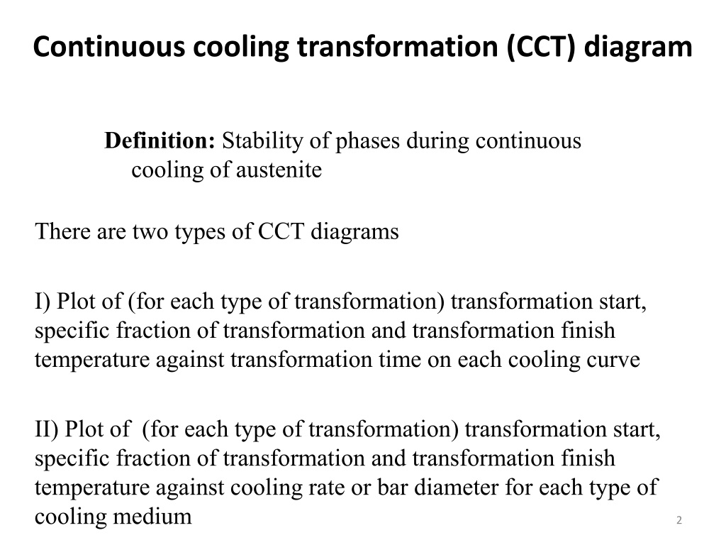
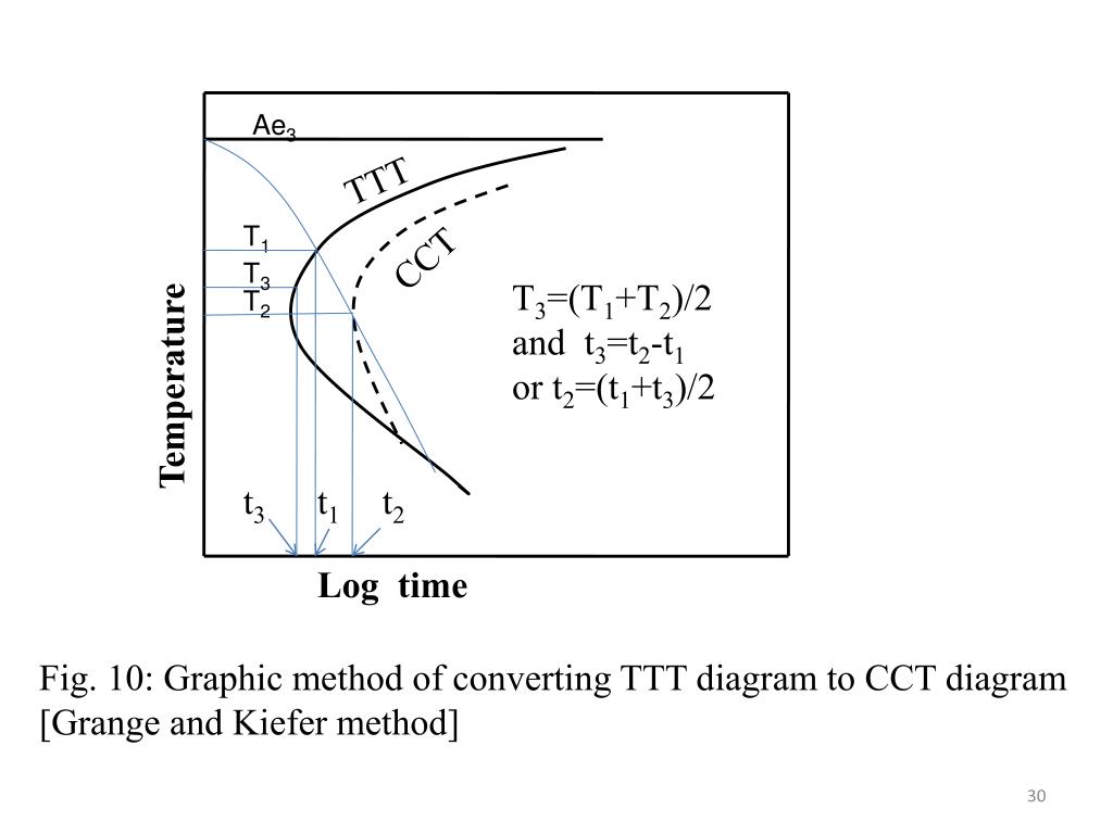
Ppt Continuous Cooling Transformation Cct Diagrams Powerpoint Cct diagrams measure the extent of transformation as a function of cooling time at continuously decreasing temperatures. the main difference from ttt diagrams is that continuous cooling does not allow for bainite formation and always results in pearlite. properties like hardness and strength depend on the formed microstructure constituents like. M. muneebrehman66. 1) continuous cooling transformation (cct) diagrams show transformation start, fraction of transformation, and finish temperatures for different transformations under continuous cooling conditions. 2) cct diagrams are determined through dilatometric measurements during continuous cooling, where sample dilation is measured to. 4. it measure the extent of transformation as a function of time for a continuously decreasing temperature. usually materials are cooled continuously, thus continuous cooling transformation diagrams are appropriate. for continuous cooling, the time required for a reaction to begin and end is delayed, thus the isothermal curves are shifted to longer times and lower temperatures main difference. Continuous cooling transformation (cct) diagrams are widely used when heat treating steels and represent which type of phase will occur in a material as it is cooled at different cooling rates. cct diagrams are constructed on the basis of dilatometry measurements on relatively small testing samples (cylindrical shape with diameter of 4mm and length of 11 mm in this study). the main aim of this.

Ppt Continuous Cooling Transformation Cct Diagrams Powerpoint 4. it measure the extent of transformation as a function of time for a continuously decreasing temperature. usually materials are cooled continuously, thus continuous cooling transformation diagrams are appropriate. for continuous cooling, the time required for a reaction to begin and end is delayed, thus the isothermal curves are shifted to longer times and lower temperatures main difference. Continuous cooling transformation (cct) diagrams are widely used when heat treating steels and represent which type of phase will occur in a material as it is cooled at different cooling rates. cct diagrams are constructed on the basis of dilatometry measurements on relatively small testing samples (cylindrical shape with diameter of 4mm and length of 11 mm in this study). the main aim of this. A continuous cooling transformation (cct) phase diagram is often used when heat treating steel. [ 1 ] these diagrams are used to represent which types of phase changes will occur in a material as it is cooled at different rates. these diagrams are often more useful than time temperature transformation diagrams because it is more convenient to. Typical continuous cooling transformation diagrams using this method are shown in [1]. these diagrams allow the prediction of hardness and microstructure in the center of any diameter bar. this is also the most common method for displaying cct diagrams. figure 1: cct diagram for aisi 1060 steel. figure 2: cct diagram for aisi 5160 steel.

Ppt Chapter 10 Phase Transformations Powerpoint Presentation Free A continuous cooling transformation (cct) phase diagram is often used when heat treating steel. [ 1 ] these diagrams are used to represent which types of phase changes will occur in a material as it is cooled at different rates. these diagrams are often more useful than time temperature transformation diagrams because it is more convenient to. Typical continuous cooling transformation diagrams using this method are shown in [1]. these diagrams allow the prediction of hardness and microstructure in the center of any diameter bar. this is also the most common method for displaying cct diagrams. figure 1: cct diagram for aisi 1060 steel. figure 2: cct diagram for aisi 5160 steel.

Comments are closed.