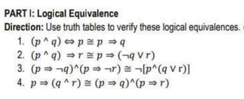
Answered Part 1 Logical Equivalence Direction Bartleby Lecture by dr. art langer, author. analysis & design of information systems (3nd ed), langer, springer verlag 2007 (isbn978 1 844628 654 4) more. Dfds are of two types: physical dfd and logical dfd. the following table lists the points that differentiate a physical dfd from a logical dfd. it is implementation dependent. it shows which functions are performed. it is implementation independent. it focuses only on the flow of data between processes.

Solved Part C Using Known Logical Equivalences Standard Chegg Data flow diagrams (dfds) are powerful visual tools representing information flow within systems. understanding their types and components is important as each type has a different purpose, and components help in creating an accurate data flow diagram (dfd). Study with quizlet and memorize flashcards containing terms like what is a data flow diagram (dfd)?, what is process modeling?, compare between the dfds and flowcharts from logical and physical systems point of view and more. In this tutorial, we will show you how to draw a context diagram, along with a level 1 diagram. note: the software we are using here is visual paradigm. you are welcome to download a free 30 day evaluation copy of visual paradigm to walk through the example below. no registration, email address or obligation is required. Data flow diagrams are usually produced using a case tool although they can be produced simply with a pencil and paper. the diagrams shown in this unit were developed using select ssadm professional version 4.1.1. using a case tool for construction of the dfds has many advantages. it is not just a drawing tool.

Solved Problem 4 6pts 3 3 Use The Logical Equivalence Chegg In this tutorial, we will show you how to draw a context diagram, along with a level 1 diagram. note: the software we are using here is visual paradigm. you are welcome to download a free 30 day evaluation copy of visual paradigm to walk through the example below. no registration, email address or obligation is required. Data flow diagrams are usually produced using a case tool although they can be produced simply with a pencil and paper. the diagrams shown in this unit were developed using select ssadm professional version 4.1.1. using a case tool for construction of the dfds has many advantages. it is not just a drawing tool. The following example is intended to illustrate the development of a data flow diagram by selectively looking at each of the components explored earlier in this chapter. this example, called “world’s trend catalog division,” will also be used to illustrate concepts covered in chapters 8 and 9. The data flow diagrams (dfds) are either classified as physical or logical. this article will define logical and physical data flow diagrams along with a comparison table. Physical data flow diagrams focus on how things happen in an information flow. these diagrams specify the software, hardware, files, and people involved in an information flow. a detailed physical data flow diagram can facilitate the development of the code needed to implement a data system. A data flow diagram of the scope of an organizational system that shows the system boundaries, external entities that interact with the system, and the major information flows between the entities and the system.

Show By Using The Logical Equivalences In Chegg The following example is intended to illustrate the development of a data flow diagram by selectively looking at each of the components explored earlier in this chapter. this example, called “world’s trend catalog division,” will also be used to illustrate concepts covered in chapters 8 and 9. The data flow diagrams (dfds) are either classified as physical or logical. this article will define logical and physical data flow diagrams along with a comparison table. Physical data flow diagrams focus on how things happen in an information flow. these diagrams specify the software, hardware, files, and people involved in an information flow. a detailed physical data flow diagram can facilitate the development of the code needed to implement a data system. A data flow diagram of the scope of an organizational system that shows the system boundaries, external entities that interact with the system, and the major information flows between the entities and the system.