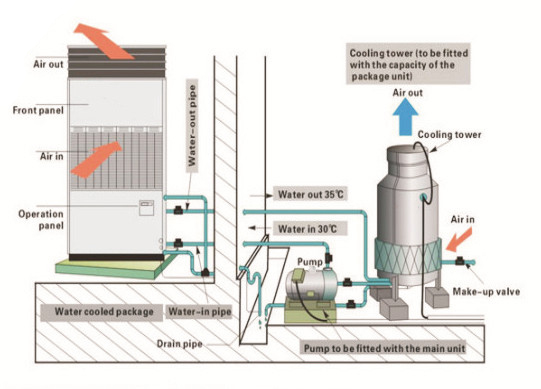
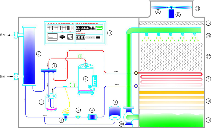
Water Cooled Package Unit Diagram

Water Cooled Package Unit Schematic Diagram 2. nominal cooling and heating capacity are based on the conditions below: cooling 27°cdb 19°cwb indoor and enter cooling water temperature 30°c, rated water flow. 3. sound pressure level test method: position of the measurement point is 1m in front and 1m below the unit. 4. the numbers in the parentheses are applicable for the units with. A water cooled package unit diagram provides a visual representation of the components and processes of a water cooled package unit system. this diagram is often used in the field of hvac (heating, ventilation, and air conditioning) to help engineers and technicians understand how the system works and troubleshoot any issues that may arise.

Water Cooled Package Unit Schematic Diagram Tpw series water cooled package unit (floor standing type) is a new generation user friendly unitary air conditioning unit launched by absorbing the latest designs at home and abroad and in combination with the actual usage. the product m featuresature technology, compact structure, simple installation, stable and reliable performance and high eer. The water cooled package the unit s shall contain refrigerant circuits, each consisting of hermetic compressor(s) and a direct expansion cooling coil complete with expansion valves and solenoid valve controls. the unit condenser(s), fan(s) and drives and air cabinet. the water cooled package split ducted system for standard rating temperatures and. Nominal cooling capacity. hwp 3.5kw ~ 44.5kw cwp 6.27kw ~ 101.6kw. heating figure based on reverse cycle. nominal heating capacity. hwp 3.7kw ~ 42.2kw cwp 6.63kw ~ 98.6kw. cycleover 60 years of innovationwe're dedicated to pioneering innovative new technologies which make installation a breeze and prov. th temperzone water cooled systemswhen. Inspiring confidence | leading innovation | carrier.
Water Cooled Package Unit Schematic Diagram Nominal cooling capacity. hwp 3.5kw ~ 44.5kw cwp 6.27kw ~ 101.6kw. heating figure based on reverse cycle. nominal heating capacity. hwp 3.7kw ~ 42.2kw cwp 6.63kw ~ 98.6kw. cycleover 60 years of innovationwe're dedicated to pioneering innovative new technologies which make installation a breeze and prov. th temperzone water cooled systemswhen. Inspiring confidence | leading innovation | carrier. Introduction. this operation manual concerns packaged water cooled water chillers of the daikin ewwd mbynn series. these units are provided for indoor installation and used for cooling applications. the ewwd units can be combined with daikin fan coil units or air handling units for air conditioning purposes. The water filter must be installed in front of the unit for removing dirt from the water to prevent damage to the unit or malfunctioning of the evaporator or condenser. the water filter must be cleaned on a regular base. table 3 water quality specifications dae water quality requirements bphe ph (25 °c) 7.5 – 9.0.

Water Cooled Package Unit Schematic Diagram Introduction. this operation manual concerns packaged water cooled water chillers of the daikin ewwd mbynn series. these units are provided for indoor installation and used for cooling applications. the ewwd units can be combined with daikin fan coil units or air handling units for air conditioning purposes. The water filter must be installed in front of the unit for removing dirt from the water to prevent damage to the unit or malfunctioning of the evaporator or condenser. the water filter must be cleaned on a regular base. table 3 water quality specifications dae water quality requirements bphe ph (25 °c) 7.5 – 9.0.

Water Cooled Package Unit Schematic Diagram

Comments are closed.