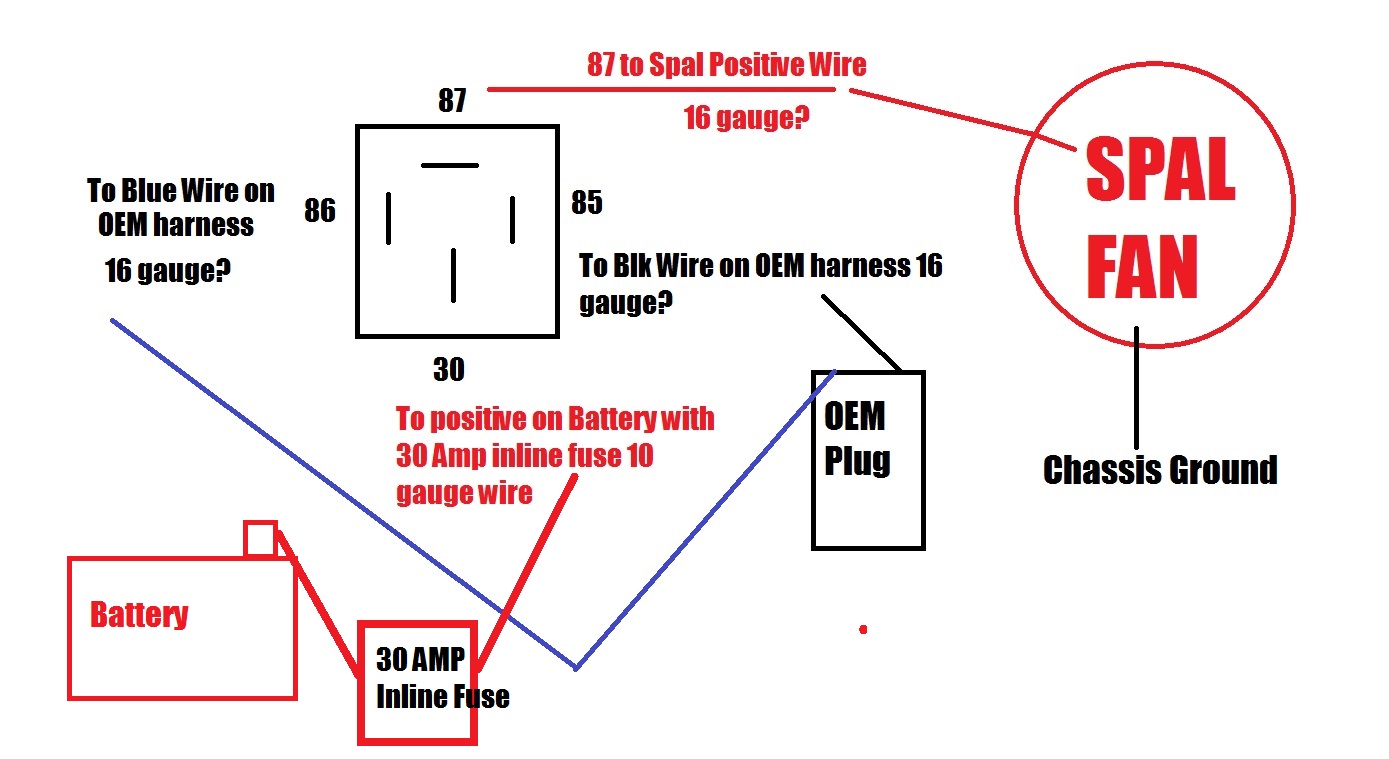
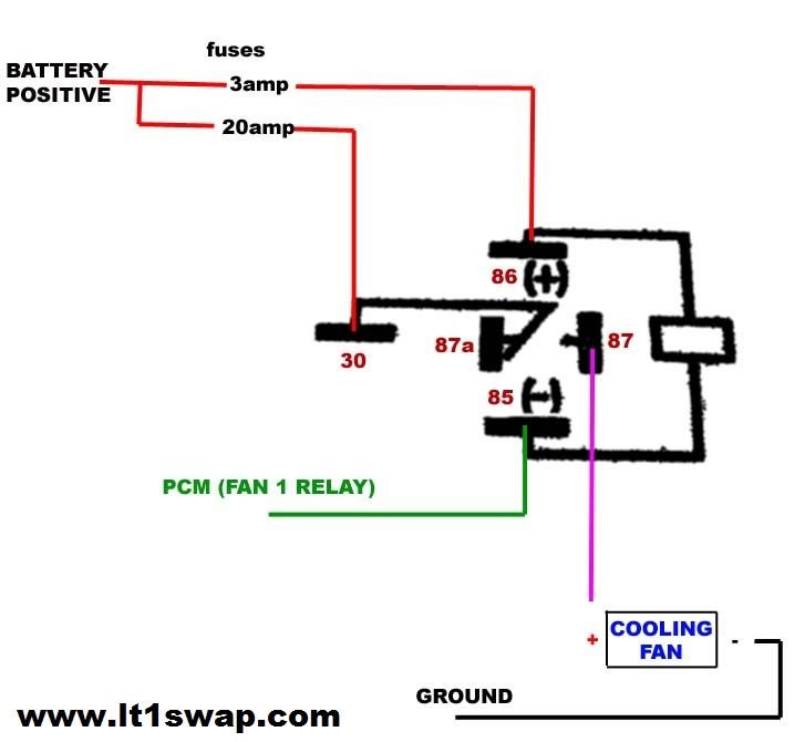
1986 Camaro Electric Fan Cooling Fan Relay Diagram

1986 Camaro Electric Fan Cooling Fan Relay Diagram вђ Otosection Typical fan wiring. the wire from 86 goes to the fan switch. in the diagram attached when the coolant reaches the set temp the switch closes and provides the ground path to the relay that closes the relay and the fans come on. when the temp drops the temp switch opens and the fans turn off. Install the temperature controlled sending unit in one of the cooling passage ports on your intake manifold, making sure to use a high temperature thread sealant to prevent leaks. the sending unit.

Diagram Electric Fan Relay Wiring Diagram For 86 Trans Am Mydiagram Diagram 1. here the relay has entire control of the fan. the temp controller is used on the low amp coil part of the circuit and the indash switch is a 3 position switch with 2 on positions and a off position. in the off position, fan is off regardless of temp and key position. The fan is controlled mechanically through an in cylinder head thermal switch and through the. mechanical a c slider switch. the in cylinder head thermal switch is designed to turn on the fan. when coolant temperatures reach 222°f (or higher) or when the a c is turned on. there is no. ecm control for the fan on single fan applications. objective. The 8 awg from the starter that runs to a splice to two 12awg wires, one going to the 1 wire alternator and 1 going to the headlight relay (40amp) and horn. i plan on changing the 8 awg to 6 for both the starter to splice and the alt to starter wire and leave the horn and relay #3 (headlights) at 12 awg. then wire the two 40 amp relays from the. Cooling fan > 5.0l system wiring diagrams 1986 chevrolet camaro 5.0l eng z28 fig 1: 5.0l (vin f), cooling fan circuit 98009 (20 ga red) hot at all times hot in run a b d2 c2 c10 c2 c1 c2 d11 c2 b a b a c e wht blk blk blk blk yel blk wht blk dk blu dk grn wht red blk org tan brn 452 410 335 532 fuse block fusible link electronic control.

Diagram Electric Fan Relay Wiring Diagram For 86 Trans Am Mydiagram The 8 awg from the starter that runs to a splice to two 12awg wires, one going to the 1 wire alternator and 1 going to the headlight relay (40amp) and horn. i plan on changing the 8 awg to 6 for both the starter to splice and the alt to starter wire and leave the horn and relay #3 (headlights) at 12 awg. then wire the two 40 amp relays from the. Cooling fan > 5.0l system wiring diagrams 1986 chevrolet camaro 5.0l eng z28 fig 1: 5.0l (vin f), cooling fan circuit 98009 (20 ga red) hot at all times hot in run a b d2 c2 c10 c2 c1 c2 d11 c2 b a b a c e wht blk blk blk blk yel blk wht blk dk blu dk grn wht red blk org tan brn 452 410 335 532 fuse block fusible link electronic control. The ecm grounds the coolant fan circuit when the coolant temperature sensor indicates the temperature is greater than 222° or when the a c head pressure is greater than 232 psi and the vehicle speed is less than 35 or 40 mph (depending on application). when this circuit is grounded, the fan relay is energized and voltage is applied to the fan. Start with taking both of the positive wires from the fans and connect them to the yellow wires on each relay. you will then need to run switched power (usually from your ignition switch, but modern replacement wiring harnesses usually have a fused fan relay trigger wire) to the blue wires on the relays. next, both of the black wires from the.

Comments are closed.