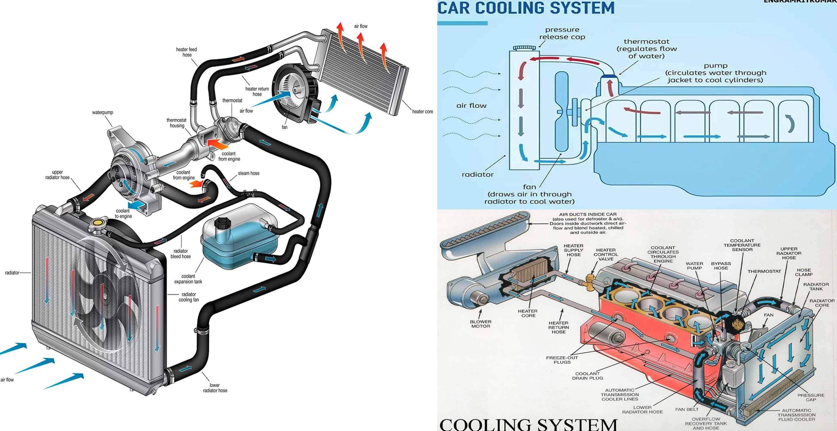
Gm 3 8 Engine Cooling System Diagram

Cooling System Diagrams For Gm 3 8 L Engine Cars 1992 buick regal custom. oil pressure sensor location please 3.8l. the oil pressure sensor is located on the passenger side of the engine down behind the power steering pump. best way to get to it is through the rear of the passenger side front wheel well. turn the wheel all the way to the left. you will see it on the engine block behind the pump. The coolant flow in the gm 3800 engine follows a well defined path, ensuring that each component receives the necessary cooling to operate efficiently. the diagram showcases the various components involved in the coolant flow, including the radiator, water pump, thermostat, and engine block. by understanding this flow, mechanics and enthusiasts.

Schematic Diagram Of Engine Cooling System The lsx cooling system (i believe that this applies to the older lt1's also but not 100% sure) the first thing that is important is to understand how this system works. here is an illustration of how the stock system works. the blue is considered the low pressure, then yellow, orange and red depicts highest pressure. The buick 231 cu. in. 3.8l v6 engine has had a production run lasting more than 30 years. like the small block chevy v8, this engine has undergone many changes over the years to keep it abreast of changing consumer expectations and emissions regulations. the first buick 3.8l was offered in the 1975 model year skyhawk, apollo, century and regal. the engine was based on an earlier 198 cu. in. v6. Second generation repairs: servicing the gm 3800 series ii engine. the gm 3800 series ii engine, introduced in 1995, is quite a different engine from its predecessor, the series i engine. while the stroke for the 3.8l engine remained at 3.4" (86 mm), and the bore remained at 3.8" (97 mm), the engine architecture changed dramatically. by ed sunkin. There are 9 components participating in the 5.3 vortec cooling system. these are the radiator, the upper and lower hose for the radiator, cap or pressure release valve, a water pump, a coolant thermostat, the thermostat housing, and a cooling fan shroud. 5.3 vortec cooling system diagram. the in depth discussion on all parts marked as a, b, c.

Comments are closed.