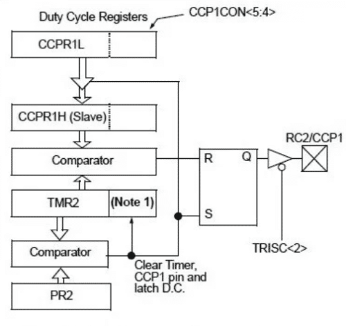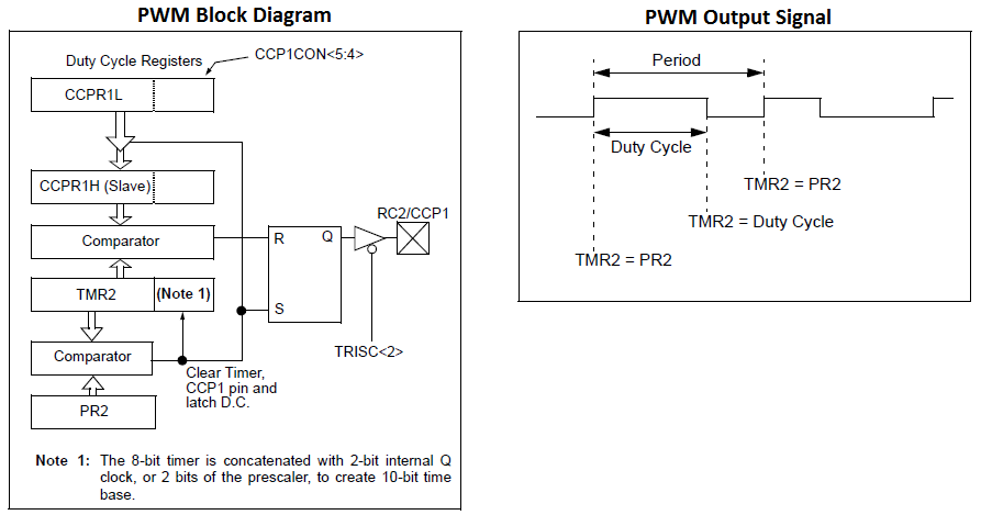
Pwm Interfacing With Pic16f877a Primer Pdf Pic Microcontroller In this tutorial we are going to discuss the pwm module of pic16f877a. first we will see how to configure the pwm registers to generate signals of required pwm, at the end we will see how to use the exploreemdedded pwm library. In this tutorial, we will learn how to generate pwm signals using pic pic16f877a. our pic mcu has a special module called compare capture module (ccp) which can be used to generate pwm signals. here, we will generate a pwm of 5 khz with a variable duty cycle from 0% to 100%.

Pic16f877a Pwm Tutorials Vrogue Co In this pwm example, we will learn to generate a variable duty cycle pulse width modulation signal using pic16f877a. we use two push buttons for each pwm channel. For the pic16f877a, this technique is used to control motor speeds, led brightness, or generate audio signals, all using a 0–5v output. the pic16f877a’s capture compare pwm (ccp) module has three modes: capture mode: records the time of an external event (e.g., measuring pulse duration). In this blog post, we’ll explore how to generate pwm signals using the pic16f877a microcontroller for motor control applications. this post will cover the basic concepts of pwm, configuring the pwm module in the pic16f877a, and how to apply it for dc motor control. Learn how to generate pwm signals on pic16f877a microcontroller with this tutorial. understand the concepts of frequency and duty cycle.

Pwm In Pic16f877a Openlabpro In this blog post, we’ll explore how to generate pwm signals using the pic16f877a microcontroller for motor control applications. this post will cover the basic concepts of pwm, configuring the pwm module in the pic16f877a, and how to apply it for dc motor control. Learn how to generate pwm signals on pic16f877a microcontroller with this tutorial. understand the concepts of frequency and duty cycle. In this tutorial we will learn to generate pwm, pulse width modulated waves using ccp module of pic 16f877a microcontroller using mplab xc8 compiler. This tutorial explains how to generate pwm signals using the pic16f877a microcontroller's ccp module with mplab and xc8 compiler. it covers producing a 5khz pwm signal with a duty cycle varying from 0% to 100%, controlled by a potentiometer via the adc. The interfacing pwm with pic16f877a program is very simple and straight forward, which generates a pulse pattern in a particular frequency. an adc signal is used to varying the duty cycle of pwm signal. Pulse width modulation (pwm) is a digital signal which is most commonly used in control circuitry. this signal is set high (5v) and low (0v) in a predefined time and speed.

Pic16f877a Pwm Tutorials In this tutorial we will learn to generate pwm, pulse width modulated waves using ccp module of pic 16f877a microcontroller using mplab xc8 compiler. This tutorial explains how to generate pwm signals using the pic16f877a microcontroller's ccp module with mplab and xc8 compiler. it covers producing a 5khz pwm signal with a duty cycle varying from 0% to 100%, controlled by a potentiometer via the adc. The interfacing pwm with pic16f877a program is very simple and straight forward, which generates a pulse pattern in a particular frequency. an adc signal is used to varying the duty cycle of pwm signal. Pulse width modulation (pwm) is a digital signal which is most commonly used in control circuitry. this signal is set high (5v) and low (0v) in a predefined time and speed.