Solved And For In The Figure Below Sketch The Following Chegg For p in the figure below, sketch the following angles onto the figure. b. • a. t 0. your solution’s ready to go! our expert help has broken down your problem into an easy to learn solution you can count on. question: and for in the figure below, sketch the following angles onto the figure. For each of the root loci shown below, state whether or not the sketch can be a root locus. if the sketch cannot be a root locus, explain all the reasons it cannot be one.

Solved 4 Consider The Following Figure A Sketch The Chegg Using the mohr’s circle, determine the normal and shear stress on the inclined plane shown in the figure and label this point as n on the mohr’s circle. Complete the timing diagram given in the figure, which shows the signal values with 1 ns resolution. there will be a slight difference in the delay from d to output dependent upon whether the d has to go through the inverter. Generate answers instantly with our ai tool, or receive a tailored solution from our expert tutors. 1. consider a three phase power system with one line diagram shown in figure 1. Solution figure 4: sketches for the resulting signals. let x(t) be the continuous time complex exponential signal x(t) = ejw0t with fundamental frequency !0 and fundamental period t0 = 2 =!0. consider the discrete time signal obtained by taking equally spaced samples of x(t) that is,.

Solved Question Chegg Generate answers instantly with our ai tool, or receive a tailored solution from our expert tutors. 1. consider a three phase power system with one line diagram shown in figure 1. Solution figure 4: sketches for the resulting signals. let x(t) be the continuous time complex exponential signal x(t) = ejw0t with fundamental frequency !0 and fundamental period t0 = 2 =!0. consider the discrete time signal obtained by taking equally spaced samples of x(t) that is,. Our expert help has broken down your problem into an easy to learn solution you can count on. here’s the best way to solve it. subdivision (a): firstly, we need to find the following signals: x (1 t) , u (t 1) and u (t 2) steps for x (1 t): 1. reverse x (t) to get x ( t) 2. shift right by 1 to get x (1 t) steps for u (t 1) and u (t 2): 1. What is the correct sketch of the two plates and the region between them, showing the distribution of positive charge on the bottom plate and electric field lines between the two plates with the correct direction of the field?. Step by step solution using mesh analysis to find current i0 in a circuit. electrical engineering problem. Sol: q9. find the value of r of the circuit below to provide vo = 2.4 v given that the diode has 0.7 v drop at 1ma.

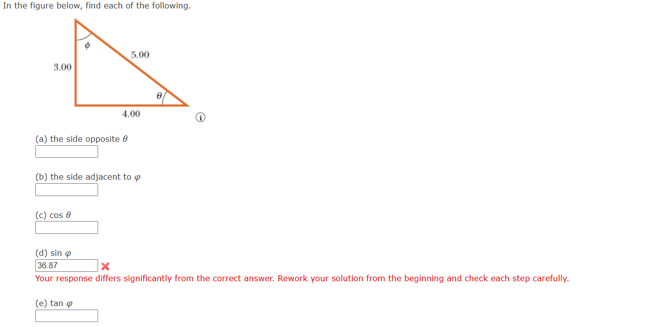
Solved In The Figure Below Find Each Of The Following Chegg Our expert help has broken down your problem into an easy to learn solution you can count on. here’s the best way to solve it. subdivision (a): firstly, we need to find the following signals: x (1 t) , u (t 1) and u (t 2) steps for x (1 t): 1. reverse x (t) to get x ( t) 2. shift right by 1 to get x (1 t) steps for u (t 1) and u (t 2): 1. What is the correct sketch of the two plates and the region between them, showing the distribution of positive charge on the bottom plate and electric field lines between the two plates with the correct direction of the field?. Step by step solution using mesh analysis to find current i0 in a circuit. electrical engineering problem. Sol: q9. find the value of r of the circuit below to provide vo = 2.4 v given that the diode has 0.7 v drop at 1ma.