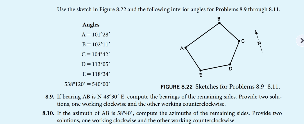
Solved Use The Sketch In Figure 8 22 And The Following Chegg Provide two solu tions, one working clockwise and the other. your solution’s ready to go! our expert help has broken down your problem into an easy to learn solution you can count on. question: use the sketch in figure 8.22 and the following interior angles for problems 8.9 through 8.11. Use the sketch in figure 8.22 and the following observed interior angles for problems 8.9 through 8.11. \ [ \begin {array} {c} \text { angles } \\ \mathrm {a}=101^ {\circ} 24^ {\prime} \\ \mathrm {b}=102^ {\circ} 10^ {\prime} \\ \mathrm {c}=104^ {\circ} 41^ {\prime} \\ \mathrm {d}=113^ {\circ} 02^ {\prime} \\ \mathrm {e}=118^ {\circ} 33.

Solved Figure 2 29 Sketch For Problem 2 7c Figure 2 31 Chegg There are 2 steps to solve this one. for the circuit shown figure 8.22 above in lab summary of theory, calculate and provide the following: a. value of r for critical damping given that l=1h and c = 1uf and is=1 a dc. b. now, enter the circuit using multisim schematic capture. Sketch the root locus for a unity feedback system for each of the following controller plant transfer functions. estimate the range of k for system stability and verify the estimate using the routh hurwitz criterion. Problem 11.1 (10 points) for the state of plane stress shown in the figure: draw the mohr’s circle and indicate the points that represent stresses on face x and on face y. Refer to the circuit shown in figure 8 2. redraw the circuit and use the following values: e (t) = 12 v r1 = 270 Ω r2 = 510 Ω r3 = 470 Ω r4 = 330 Ω assume that an ammeter indicates a total circuit current of 15 ma. a voltmeter indicates the following voltage drops across each resistor: e1 = 12 v e2 = 0 v e3 = 7 v e4 = 5 v.

Solved Figure 8 22 Refer To Figure 8 22 Suppose The Chegg Problem 11.1 (10 points) for the state of plane stress shown in the figure: draw the mohr’s circle and indicate the points that represent stresses on face x and on face y. Refer to the circuit shown in figure 8 2. redraw the circuit and use the following values: e (t) = 12 v r1 = 270 Ω r2 = 510 Ω r3 = 470 Ω r4 = 330 Ω assume that an ammeter indicates a total circuit current of 15 ma. a voltmeter indicates the following voltage drops across each resistor: e1 = 12 v e2 = 0 v e3 = 7 v e4 = 5 v. Using the slope deflection method, compute the end moments and plot the bending moment diagram. also, sketch the deflected shape of the beam. the beam has constant ei for both the spans. solution. (a) fixed end moments. treating each span as a fixed beam, the fixed end moments are as follows: (b) slope deflection equations. Provide two solutions, one working clockwise and the other. your solution’s ready to go! our expert help has broken down your problem into an easy to learn solution you can count on. question: use the sketch in figure 8.22 and the following interior angles for problems 8.9 through 8.11. Sketch the results on each element. determine the equivalent state of stress on an element at the same point which represents (a) the principal stress, and (b) the maximum in plane shear stress and the associated average normal stress. Consider the circuit shown in figure (a). il(0 ) = 0, and vr(0 ) = 0. but, vr(0 ) vc(0 ) 10 = 0, or vc(0 ) = 10v. (a) at t = 0 , since the inductor current and capacitor voltage cannot change abruptly, the inductor current must still be equal to 0a, the capacitor has a voltage equal to –10v.

Solved Figure 2 22 Sketch For Problem 2 2 2 3 Given A Chegg Using the slope deflection method, compute the end moments and plot the bending moment diagram. also, sketch the deflected shape of the beam. the beam has constant ei for both the spans. solution. (a) fixed end moments. treating each span as a fixed beam, the fixed end moments are as follows: (b) slope deflection equations. Provide two solutions, one working clockwise and the other. your solution’s ready to go! our expert help has broken down your problem into an easy to learn solution you can count on. question: use the sketch in figure 8.22 and the following interior angles for problems 8.9 through 8.11. Sketch the results on each element. determine the equivalent state of stress on an element at the same point which represents (a) the principal stress, and (b) the maximum in plane shear stress and the associated average normal stress. Consider the circuit shown in figure (a). il(0 ) = 0, and vr(0 ) = 0. but, vr(0 ) vc(0 ) 10 = 0, or vc(0 ) = 10v. (a) at t = 0 , since the inductor current and capacitor voltage cannot change abruptly, the inductor current must still be equal to 0a, the capacitor has a voltage equal to –10v.

Solved Sketch Chegg Sketch the results on each element. determine the equivalent state of stress on an element at the same point which represents (a) the principal stress, and (b) the maximum in plane shear stress and the associated average normal stress. Consider the circuit shown in figure (a). il(0 ) = 0, and vr(0 ) = 0. but, vr(0 ) vc(0 ) 10 = 0, or vc(0 ) = 10v. (a) at t = 0 , since the inductor current and capacitor voltage cannot change abruptly, the inductor current must still be equal to 0a, the capacitor has a voltage equal to –10v.

Solved Sketch This Chegg